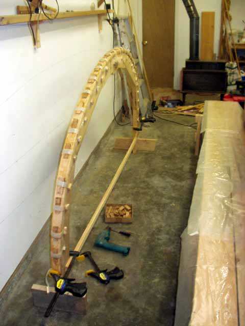
I used modified hull molds as a form to shape my frame laminations The
molds were trimmed down so that the frame passes over the limber holes in a smooth arc The cut off pieces were then used as a template for the bilge blocks Below, half of a frame, made of four 12 foot laminations had just been epoxied, strapped and wedged to the form Two of these epoxied together in the hull make up a full frame.
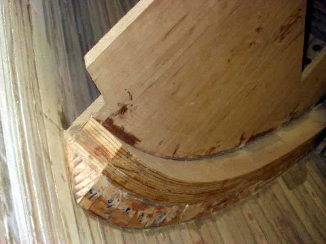
Below is the bulkhead at the aft end of the cockpit where the bevels are more extreme The notch at the top was for the deck clamp I decided to wait and install the rest of the bulkheads after the deck clamp and bulwark longitudinals were laminated in place This allowed me to work from inside of the hull, which saved a lot of steps.
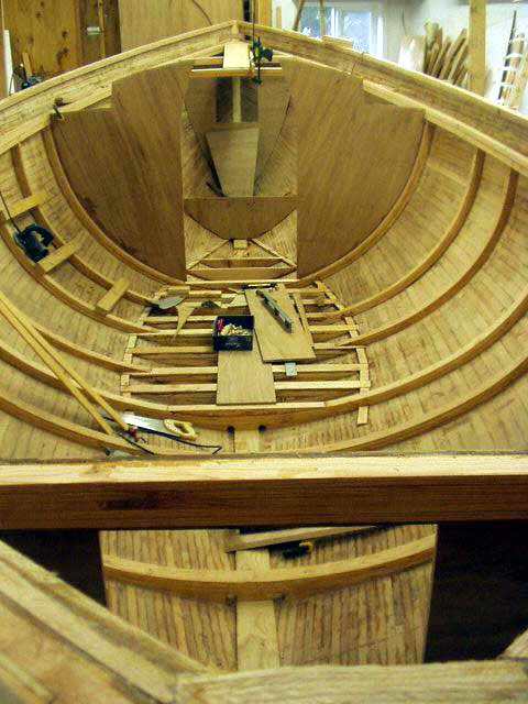
September, 2003 The sole cleats, frames, floors, breasthooks and centerplank are installed.
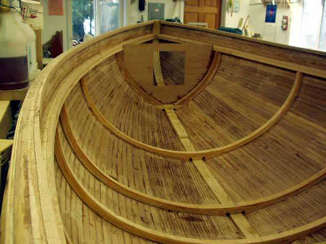
January 2003, looking aft The deck clamp and bulwark logitudinals had just been epoxied in place and faired to finish level The floors and frames are laminated and installed Each bulkhead will be epoxied joined to the hull with a frame.
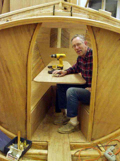
November, 2003 Vee berth with dining table finished and mast beam in position I have been concerned for the past 8 years how well I would fit at the table So, I'm pleased to see that it works as planned.
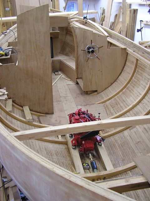
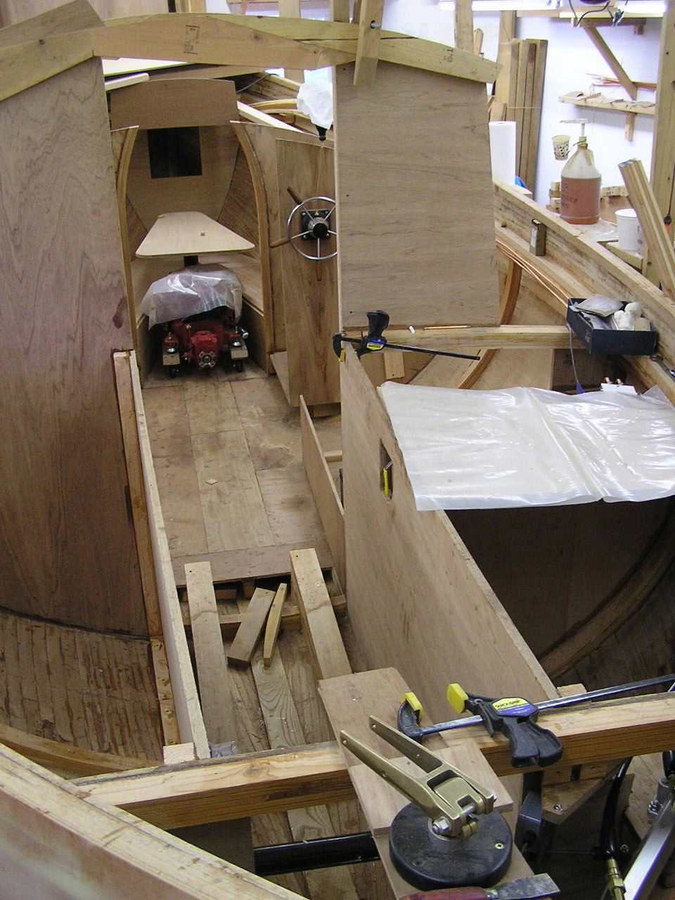
March 4, 2005 The engine finally arrived and is set on it's beds The subsole, galley bulkheads and the helm pump are installed I made the decision to use hydraulics for the steering because it makes connecting the two steering stations and the autopilot so much simpler and less expensive as well.
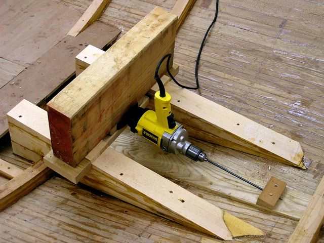
My reason for getting the engine at this stage was primarily to make installing the beds easier There is so little room once the engine room bulkheads are installed that I wanted to get this out of the way while I could still get to it This is my first try for drilling the shaft hole The drill slides on the engine beds, set down the same distance as the shaft is from the motor mounts.
Doing a mockup with a prop and skeg templates in place, my first hole provided perfect clearance under the crankcase pan but not enough clearance for access to the stuffing box. By flatten the beds, this lowered the front of the engine and raised the aft end enough for access and still left the required clearance above the prop. So, I plugged and re-drilled the shaft hole I was fortunate to have done this before installing the cockpit bulkheads as it would have been very difficult to have done it later.
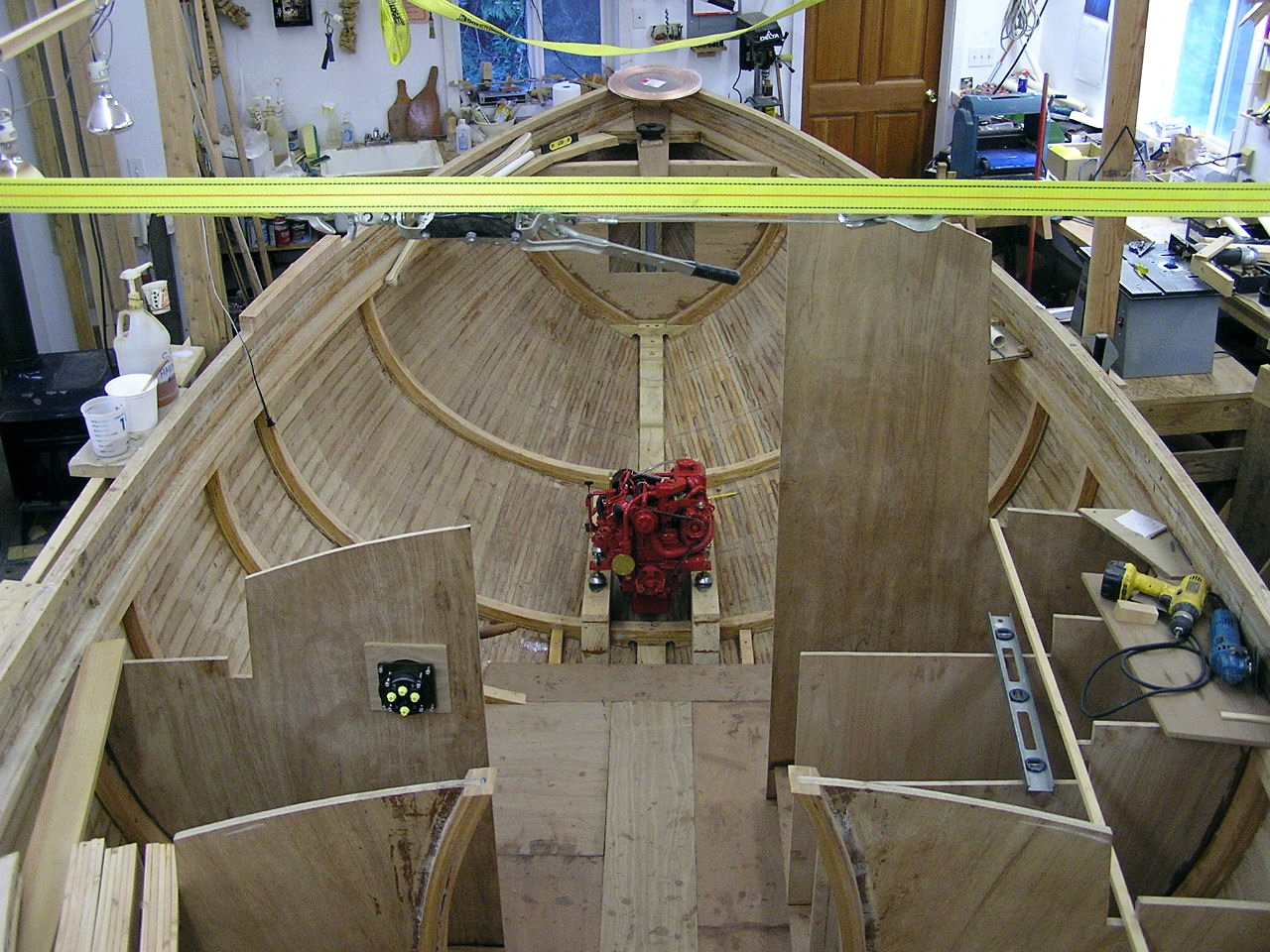
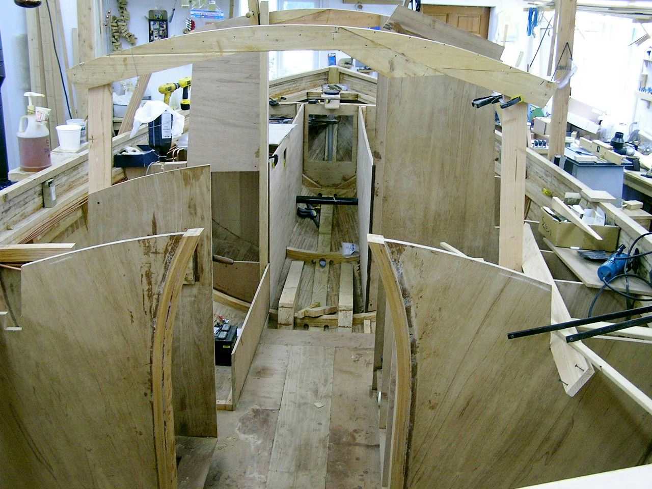
The yellow straps running crosswise are to restore the correct cross section in the mid section Springback, when the hull was freed from the molds, caused the center area to spring out a little over an inch This also resulted in a slight increase in rocker I secured the bottoms of four 2x4's to the concrete floor with anchor bolts and the tops are pulled together with come-a-longs and straps There are 2x4's on the outside of the hull on both sides to distribute the load from the verticals The center area now measures within 1/8" on all frames Once installed, the 18" wide side decks will retain the shape and I will be able to remove the braces For now, they are well out of the way and actually come in handy once in a while.
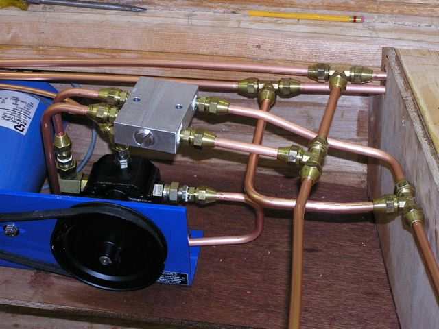
April 29, 2005 - All the copper tubing has been replaced with new and tested under pressure The flares that I had initially made were faulty and all leaked (I found it was impossible to make a flare seal if you follow the instructions on the packaging that comes with the flaring tools.) In this view, the lines to the left go to the helm, the lines toward the camera are to the bypass valve, and the lines to the right to the cylinder The motor and pump are for the autopilot The bypass valve is to use the tiller in the cockpit.
May 20, 2005 - I moved the engine out of the way to allow room to place the engine and aft cabin bulkheads The open space is disappearing quickly.
This is looking aft down the aisle.
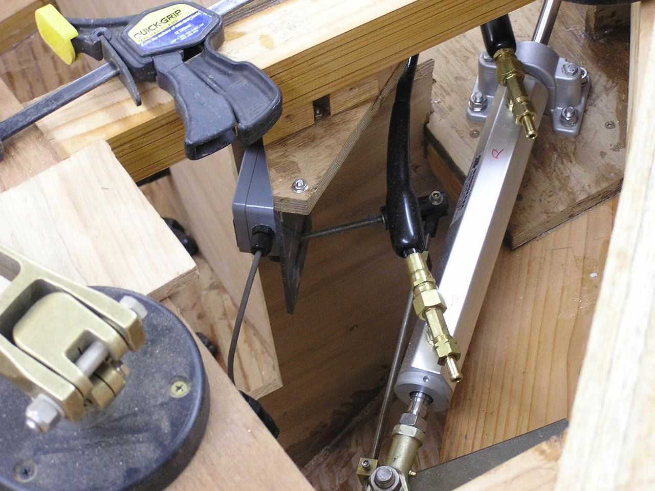
This is the RAT (rudder angle transmitter) unit tucked in the aft compartment (under the clamp handle) I will install a screw in deck hatch cover over this area as it will be hard to reach everything otherwise The hydraulic cylinder and hoses are mounted on a 2" thick shelf that spans through the aft bulkhead I will be adding the rudder stops, the exhaust pipe, exhaust check valve and through hull and backing blocks for the aft deck cleats in this compartment yet.