Construction of Al's 26, The Hull
 Construction began in April 1995 with the lofting of the lines. I chose a method
of my own design by overlaying parabolas on the design sections that are provided in the plans. The primary reason for doing this is that the entire mold section can be much more exactly defined by only five points. The plans contain 11 points, but it takes skill to draw a fair curve between the points. With parabolas, it is completely mechanical and exact. I had gone through this with several designs and found it produced better results with much less effort.
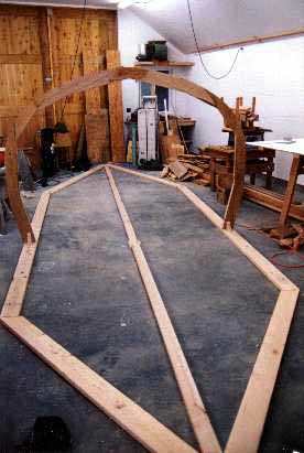
I did the lofting on the north wall of the shop so that it could be preserved throughout construction. The wall was built with this in mind. The five points (seven lines) were transferred to the layout board with a stick and the sections drawn to outside of the hull. Using the lofting wall, I was able to pick off the plank thickness allowances, which were used to transfer the cut lines directly to the molds on the layout board. The molds were built up from 2x6 fir studs. Starting at the bow end, I used splines between the mold sections, but I switched to overlapping the 2x6's later and found it a much preferred method.
Construction began in April 1995 with the lofting of the lines. I chose a method
of my own design by overlaying parabolas on the design sections that are provided in the plans. The primary reason for doing this is that the entire mold section can be much more exactly defined by only five points. The plans contain 11 points, but it takes skill to draw a fair curve between the points. With parabolas, it is completely mechanical and exact. I had gone through this with several designs and found it produced better results with much less effort.
I did the lofting on the north wall of the shop so that it could be preserved throughout construction. The wall was built with this in mind. The five points (seven lines) were transferred to the layout board with a stick and the sections drawn to outside of the hull. Using the lofting wall, I was able to pick off the plank thickness allowances, which were used to transfer the cut lines directly to the molds on the layout board. The molds were built up from 2x6 fir studs. Starting at the bow end, I used splines between the mold sections, but I switched to overlapping the 2x6's later and found it a much preferred method.
 The legs of the molds were cut so that they fell flush with the base and were aligned to a centerline wire down the middle of the base. Considerable time had to be spent tweaking the molds to allow battens to lie fair over all portions. I later determined that this was due to warpage in the lumber and unevenness in the floor on which the molds were glued up.
Doing it over, I would run all the boards over the jointer and do the layup on high density particle board to insure the molds were true. The molds were notched and the keelson and stems laminated in place. It took me less than one month to do the lofting, make all 22 molds, attach the base to the concrete floor with anchor bolts and erect all the molds. I spent another two weeks truing it all up before I could begin planking.
The legs of the molds were cut so that they fell flush with the base and were aligned to a centerline wire down the middle of the base. Considerable time had to be spent tweaking the molds to allow battens to lie fair over all portions. I later determined that this was due to warpage in the lumber and unevenness in the floor on which the molds were glued up.
Doing it over, I would run all the boards over the jointer and do the layup on high density particle board to insure the molds were true. The molds were notched and the keelson and stems laminated in place. It took me less than one month to do the lofting, make all 22 molds, attach the base to the concrete floor with anchor bolts and erect all the molds. I spent another two weeks truing it all up before I could begin planking.
 I quickly found that the 2" x 5/8" meranti planks would not bend along the sheer line as they were too stiff in the vertical direction. By laying battens ahead, I could see that by cutting the first half dozen planks down to 1" at about the 2/3rds point from the bow, I would be able to use the 2" planks, so that's what I did. After only a very few untapered planks, I discovered that the planks were too stiff to bend in the other direction, so this was resolved by tapering the ends of the planks. This continued until about the last four planks, which were quite short ones, so the hull was mostly carvel edge glued rather than the normal strip built hull. After the halfway point, the turn of the planks near the aft stem was so tight, that I had to use 1" planks and taper them down to 3/8" at the extream end to get them to lie true.
Drywall screws were used to secure the planks at each mold and I used additional blocks and screws to bring the planks flush with each other as I went. The joining surfaces were rolled with unthickened epoxy and then thickened epoxy applied to both surfaces while the plank was supported in the inverted position. Drywall screws in the end of each plank set in wires from the ceiling held the planks until they were flipped and the center secured using an index mark. Sil-Bronze screws were used to attach the ends of the planks to the stems. The planks were scarfed to about 28 feet long such that the scarf joints were staggered. The planks were run through a thickness planer after scarfing.
I quickly found that the 2" x 5/8" meranti planks would not bend along the sheer line as they were too stiff in the vertical direction. By laying battens ahead, I could see that by cutting the first half dozen planks down to 1" at about the 2/3rds point from the bow, I would be able to use the 2" planks, so that's what I did. After only a very few untapered planks, I discovered that the planks were too stiff to bend in the other direction, so this was resolved by tapering the ends of the planks. This continued until about the last four planks, which were quite short ones, so the hull was mostly carvel edge glued rather than the normal strip built hull. After the halfway point, the turn of the planks near the aft stem was so tight, that I had to use 1" planks and taper them down to 3/8" at the extream end to get them to lie true.
Drywall screws were used to secure the planks at each mold and I used additional blocks and screws to bring the planks flush with each other as I went. The joining surfaces were rolled with unthickened epoxy and then thickened epoxy applied to both surfaces while the plank was supported in the inverted position. Drywall screws in the end of each plank set in wires from the ceiling held the planks until they were flipped and the center secured using an index mark. Sil-Bronze screws were used to attach the ends of the planks to the stems. The planks were scarfed to about 28 feet long such that the scarf joints were staggered. The planks were run through a thickness planer after scarfing.
 After fairing the hull using longboards and epoxy fairing compound, the first layer of 1/8" fir veneer was applied using staples. I used 1" wide strips of 60 mil poly strips under the staples, mostly to protect the veneer from being crushed, but it also helped in removing the staples. This layer went quite quickly as there was very little fitting that had to be done.
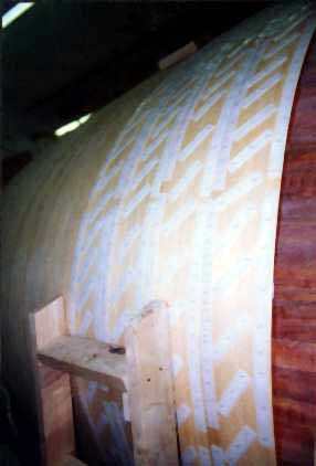
What I didn't find out until I was through was that in my concern to not have any voids under the veneer, I got it so thick that I ended up with a quilting effect, where the veneer wasn't stiff enough to squeeze the epoxy out from between the staples. This can be seen in the next photo. I again coated both surfaces with unthickened epoxy but I only spread thickened epoxy on the hull before attaching the veneers. I would start stapling in the centers of each piece, and work to the outside, with the theory that excess epoxy is squeezed out this way.
After fairing the hull using longboards and epoxy fairing compound, the first layer of 1/8" fir veneer was applied using staples. I used 1" wide strips of 60 mil poly strips under the staples, mostly to protect the veneer from being crushed, but it also helped in removing the staples. This layer went quite quickly as there was very little fitting that had to be done.
What I didn't find out until I was through was that in my concern to not have any voids under the veneer, I got it so thick that I ended up with a quilting effect, where the veneer wasn't stiff enough to squeeze the epoxy out from between the staples. This can be seen in the next photo. I again coated both surfaces with unthickened epoxy but I only spread thickened epoxy on the hull before attaching the veneers. I would start stapling in the centers of each piece, and work to the outside, with the theory that excess epoxy is squeezed out this way.
 The second layer of veneer went on fore and aft, some pieces being over 12" wide and usually one 17 foot long piece on each plank. Such large pieces over an area with this much curve sometimes presents problems that can't be remedied during the stapling process.
In a few cases, I couldn't get a particular edge to lie flat no matter how many staples I used. These small sections had to be chiseled out after the epoxy cured and new veneer pieces scarfed back in. Fortunately, I wasn't bright finishing this hull, so I could do such things. Around 30,000 staples were used on the hull. A few broke off during removal and had to be dug out much as a sliver might be.
The second layer of veneer went on fore and aft, some pieces being over 12" wide and usually one 17 foot long piece on each plank. Such large pieces over an area with this much curve sometimes presents problems that can't be remedied during the stapling process.
In a few cases, I couldn't get a particular edge to lie flat no matter how many staples I used. These small sections had to be chiseled out after the epoxy cured and new veneer pieces scarfed back in. Fortunately, I wasn't bright finishing this hull, so I could do such things. Around 30,000 staples were used on the hull. A few broke off during removal and had to be dug out much as a sliver might be.
 The outer stems were laminated in place. Since there was nothing to clamp to, I used 18" long plastic straps with wedges. This, I discovered, is the absolute best way to laminate strips. The wedges can be inserted just snug but not tight. This allows the pieces to be shifted around until they fit perfectly and then the wedges gradually tightened until epoxy squeezes out everywhere it's supposed to. It was a pleasure to do compared to having to use clamps.
After this followed the final longboarding and fairing. I found that by using three different thickness of longboard and applying epoxy thickened with silica with a notched spreader, I could make better progress than using soft fillers in the epoxy. The secret was to have the mix thick enough that it didn't sag and set up in little ridges, about 3/16" apart. Longboarding then was not over the whole surface but just taking down the ridges on the high spots, which is only a small percentage of the whole area. The subsequent layer then is put on such that the ridges are in a direction diagonal to the prior layer and all the grooves are filled in at the same time.
The outer stems were laminated in place. Since there was nothing to clamp to, I used 18" long plastic straps with wedges. This, I discovered, is the absolute best way to laminate strips. The wedges can be inserted just snug but not tight. This allows the pieces to be shifted around until they fit perfectly and then the wedges gradually tightened until epoxy squeezes out everywhere it's supposed to. It was a pleasure to do compared to having to use clamps.
After this followed the final longboarding and fairing. I found that by using three different thickness of longboard and applying epoxy thickened with silica with a notched spreader, I could make better progress than using soft fillers in the epoxy. The secret was to have the mix thick enough that it didn't sag and set up in little ridges, about 3/16" apart. Longboarding then was not over the whole surface but just taking down the ridges on the high spots, which is only a small percentage of the whole area. The subsequent layer then is put on such that the ridges are in a direction diagonal to the prior layer and all the grooves are filled in at the same time.